Introduction
Imagine if we still used those old supplies in today’s high-demand electronics market. With global electronic sales reaching nearly $2 trillion by 2021 (Source: Statista), excess energy usage would be astronomical. SMPS technology not only saves this energy but also leads to less heat dissipation, reducing the need for bulky cooling systems.
Market trends indicate a significant shift toward the adoption of SMPS. By the early 2020s, a substantial number of new electronic devices were predicted to feature SMPS circuits, reflecting their increasing importance in product design (Source: MarketsandMarkets).
What is SMPS
SMPS epitomize efficiency in power conversion, markedly outperforming traditional linear regulators by minimizing energy losses. Utilizing rapid switching mechanisms, operating at high frequencies, SMPS units achieve efficiencies upwards of 85% — a stark contrast to the 40-60% typical of linear alternatives. Consequently, for every 100 watts drawn, an SMPS proficiently delivers 85 watts, with a mere 15-watt dissipation of excess power. This not only translates to significant energy and cost savings but also mitigates thermal management challenges.
Compactness is another hallmark of SMPS design, dispensing with the bulk of large transformers and heat sinks, a critical advantage in the manufacturing of lightweight, portable electronics such as laptops and smartphones.
Additionally, the consistent voltage output of SMPS technology safeguards sensitive electronic components against power irregularities, thereby bolstering device reliability and prolonging lifespan.
How SMPS Circuit Works

-
AC Mains: This is the alternating current (AC) input from the power grid.
-
AC Rectifier and Filter: The AC input is first rectified by a set of diodes, which convert the AC to unidirectional current. The rectifier is typically a full-wave bridge rectifier. The filter, often a capacitor, then smooths out the rectified AC to reduce ripple voltage resulting in a pulsating DC.
-
Switch (Chopper): The smoothed DC is then fed to a switch, commonly a transistor that chops the DC at a high frequency. The high switching frequency allows for a smaller size of the passive components like transformers and filters that follow in the circuit.
-
Step Down Transformer: The rapidly switching DC is passed through a transformer, which steps down the voltage level. Since the power is being switched on and off quickly, the transformer can be much smaller than one needed at the mains frequency.
-
DC Rectifier and Filter: The transformer’s secondary winding outputs AC, which needs to be rectified again. This is usually done with diodes or synchronous rectification. The output is then filtered to produce a smooth DC signal.
-
Regulator (Control Circuit): Finally, a regulator (often implemented with a feedback control system) maintains a constant output voltage despite variations in input voltage or load conditions. It adjusts the operation of the switch to control the energy sent to the transformer and thus the output voltage and current.
SMPS Topologies
-
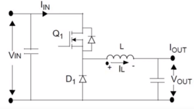
Buck Converter
During the “on” phase, Q1 conducts, allowing current to pass through the inductor (L), which accumulates energy within its magnetic field, simultaneously ensuring the continuity of inductor current. Upon deactivation of Q1, the magnetic field within the inductor collapses, which perpetuates the flow of current towards the load, now via diode D1.
A capacitor is incorporated into the design to stabilize the output voltage and sustain the correct polarity. The precise output voltage is controlled by modulating the duty cycle of Q1 — the proportion of the “on” time relative to the “off” time. By adjusting this duty cycle, the buck converter can consistently deliver a regulated output voltage that is less than the input voltage, aligning with the requirements of the load.
-
Boost Converter
-
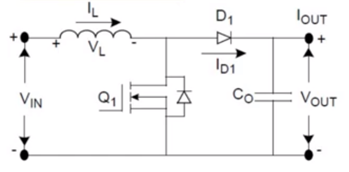
Buck-Boost Converter
The bridge rectifier at the input converts AC to DC. The DC voltage is then processed by a switch (typically a transistor), controlled by a driver IC, which switches the current flow through an inductor. Depending on the duty cycle of the switch, the inductor either boosts the voltage (when the switch is open) or bucks it (when the switch is closed), hence the name buck-boost converter. The output capacitor (Cout) smooths the output voltage to provide a stable DC output.
This configuration is often used in applications where the input voltage can vary above and below the output voltage level, requiring both step-up and step-down conversion.
-
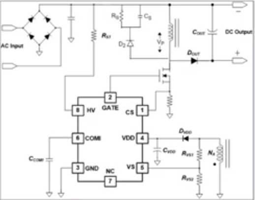
Flyback Converter
-
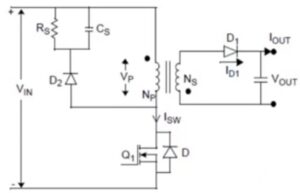
Forward Converter
Overview Table
|
Feature/Type
|
Buck Converter
|
Boost Converter
|
Buck-Boost Converter
|
Flyback Converter
|
Forward Converter
|
|
Basic Function
|
Converts a higher input voltage to a lower, stable output voltage
|
Converts a lower input voltage to a higher output voltage
|
Combines the functions of buck and boost converters; can increase or decrease voltage
|
Provides electrical isolation and voltage conversion, can step-up or step-down
|
Provides electrical isolation, commonly used for stepping down voltage
|
|
Topology
|
Single switch, single inductor, no isolation
|
Single switch, single inductor, no isolation
|
Single switch, single inductor, no isolation
|
Transformer-based, provides isolation, single or multiple outputs
|
Transformer-based, provides isolation, usually single output
|
|
Efficiency
|
High (typically over 90%)
|
High (typically over 90%)
|
High but usually less than separate buck or boost converters
|
Medium to high but lower than non-isolated topologies
|
High, but generally lower than flyback converters
|
|
Output Ripple
|
Low
|
Medium
|
High
|
Medium to high (depends on design)
|
Low to medium
|
|
Complexity/Cost
|
Low
|
Low
|
Medium
|
High (requires isolation transformer)
|
Medium to high
|
|
Applications
|
Power modules, battery chargers
|
LED drivers, battery-powered devices
|
Battery charging and discharging systems, renewable energy systems
|
Switched-mode power supplies, isolated converters
|
Low power AC/DC supplies, electronic transformers
|
|
Regulation Range
|
Limited, only below input voltage
|
Wide, output voltage can be much higher than input
|
Wide, output can be above or below input
|
Wide, adjustable via turns ratio of transformer
|
Wide but limited by transformer turns ratio and switch stress
|
|
Main Advantages
|
Simple, high efficiency, low cost
|
High voltage can be achieved without complex control
|
High flexibility for various voltage conversions
|
Provides isolation, suitable for multiple outputs
|
Higher efficiency and lower output ripple compared to flyback topology
|
|
Main Disadvantages
|
Output voltage is limited to below input voltage
|
Cannot step down voltage
|
Higher output ripple and less intuitive
|
More complex control, higher cost
|
Relatively complex, may require auxiliary winding
|
Designing an SMPS Circuit
-
Component Selection:
-
Transformers: Choose a transformer that matches your circuit’s needs—for instance, a 20W power supply operating at 85-265VAC input would benefit from a transformer rated at 24V/1A output. Inadequate rating may cause losses or thermal issues.
-
Switching Elements: Opt for a MOSFET like the IRF540N for its high current capacity (33A) and fast switching (77ns on-time) to ensure your SMPS operates efficiently without switching losses.
-
Capacitors: Select low-ESR capacitors, which can handle ripple currents and have high endurance, rated at 35V when your circuit operates at 24V, to provide a margin for voltage spikes and improve longevity.
-
-
Topology Choice:
-
Flyback, Forward, Push-Pull, Half-Bridge, and Full-Bridge converters each present a distinct set of advantages and drawbacks, contingent upon the required output power level and the degree of complexity that can be managed effectively. For applications that necessitate low to medium power output, the Flyback converter is frequently selected owing to its inherent simplicity and ease of implementation.
-
-
Control Scheme:
-
When determining the appropriate control methodology for your application, it is crucial to assess the necessity for a basic fixed-frequency controller versus an advanced solution incorporating synchronous rectification for enhanced efficiency. Controllers utilizing Pulse-Width Modulation (PWM) are standard in the industry for modulating output; however, they necessitate meticulous calibration of both frequency and duty cycle to ensure optimal performance.
-
-
Thermal Management:
-
Determine the requisite thermal management strategy and engineer a suitable thermal dissipation system. Incorporate the utilization of heat sinks on power components, taking into account the necessity for sufficient space to facilitate optimal airflow. It is imperative to mitigate the risk of overheating which can diminish the longevity of the components and may precipitate the malfunction of the Switched-Mode Power Supply (SMPS).
-
-
Protection Features:
-
Design specifications should encompass robust protection strategies to shield the circuit from overvoltage, overcurrent, and overtemperature anomalies, thus preserving its operational integrity. It is also recommended to embed a soft-start feature within the system architecture. This will serve to regulate the inrush current at the commencement of the power-up cycle, providing a safeguard against the risk of damage to electronic elements.
-
-
PCB Layout:
-
Ensure that traces carrying high current are both wide and succinct to mitigate voltage drops and circumvent potential interference. It is imperative to maintain a distinct separation between high voltage components and low voltage control circuitry to preclude noise coupling. Furthermore, the positioning of the switching element should be in close proximity to the transformer, which is essential to minimize parasitic effects and reduce electromagnetic interference (EMI) for optimal performance.
-
Advantages of Using SMPS
First, we talk efficiency. SMPS are champions here, often reaching 80-90% efficiency. That’s a big jump from the 40-60% of linear supplies. Imagine a scenario where two power supplies consume 100 watts from the wall. The SMPS might only waste 10-20 watts as heat, while a linear might lose 40-60 watts, resulting in less power loss. Over time, this adds up, saving energy and money, especially in high-power applications.
Now, size and weight – crucial for portable devices. High-frequency operation of SMPS means smaller transformers, resulting in lighter, smaller units. For example, a laptop’s power supply is small enough to fit in your hand, largely thanks to SMPS technology. In contrast, an old-fashioned linear power supply could be as big as a brick.
Then there’s load and line regulation. With SMPS, the output stays stable, no matter if the input voltage changes or if different amounts of power are drawn. This means your devices work smoothly without interruption and reach a steady state. A typical SMPS might maintain a voltage regulation within +/- 0.5% despite changes, whereas a linear supply might fluctuate up to +/- 5% volts.
Lastly, less heat equals less cooling. Because SMPS are more efficient, they turn less power into wasted heat. This means smaller heat sinks and fans, making the whole unit cheaper and more reliable. Think of a buzzing, hot power adapter versus a cool, silent one—that’s the difference SMPS can make.

