Power supplies are used in almost every electrical/electronic application to provide sufficient current at a required voltage. There are two main types of power supplies: linear and switched-mode. Both can be used interchangeably but switched-mode power supplies are getting more and more popular.
In this article, let’s have a look at what switched-mode power supplies are, how they work and their benefits and drawbacks compared to a traditional linear power supply.
What is a Switch Mode Power Supply (SMPS)?
A switched mode power supply (also known as switching power supply, SMPS, switcher) is an electronic power supply device that converts electrical power from one voltage to another efficiently.
Typically, SMPS is used to transfer power from a DC/AC source to a DC load (i.e. a computer, mobile phone, etc.). Most switched-mode power supplies convert a higher voltage (110V or 220V AC) to a much lower DC voltage like 24V, 12V, or 5V.
We can find these types of power supplies in almost every electrical appliance, especially those of which are compact. For example, mobile phone charging adapters, computers, laptop charging adapters can be taken.
History of Switched Mode Power Supplies
The history of switched-mode power supplies goes back as far as 1836. There is evidence that inductive coils have been used to generate high voltage spikes for experiments. Fast-forwarding almost a decade, in 1959 at Bell Labs, Mohamed M. Atalla and Dawon Kahng invented the power MOSFET. Power MOSFETs are the most widely used switching device in switched-mode power supplies even to date.
There are records of patents filed by IBM in 1958, where it shows a design of an SMPS based on transistor oscillation. Around the same year, General Motors Corporation (GM) also filed similar patents for SMPS designs.
The first commercial and widely known product to have a switched-mode power supply was Hewlett Packard’s HP-35 pocket calculator. The miniature SMPS was used to power the LEDs, ROM, and other primary elements like clock and registers. Although the designs have been emerging from many major vendors, the patent to use the term ‘Switched Mode Power Supply (SMPS)’ was filed in 1976 by Microchip Technology. They released the first integrated controller for switched-mode power supplies.
What Does ‘Switching Mode’ Mean?
The term ‘switched mode’ or ‘switching mode’ comes from the operation of the SMPS. An SMPS consists of a complex circuit that operates at a very high frequency (20kHz to 10MHz). This high-speed switching enables the switched-mode power supply to convert electrical power more efficiently than traditional linear power supplies.
Switch Mode Power Supply Working Principle
A switched-mode power supply consists of a complex circuit that contains a series of power electronic subcircuits to efficiently convert the power from one voltage to another.
A typical SMPS has the following block diagram with these key subsections:
- Input stage
- Switching stage
- Output stage
- Control Circuit
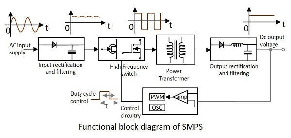
Input Stage
The power input stage generally consists of a full or half-bridge rectifier circuit that takes AC power as input and outputs a filtered DC output of the same voltage. For example, this stage can convert 110V AC to 110V DC. This stage also contains additional LC filters (inductor and capacitor) to further remove any ripples from the input power.
High-Frequency Switch
This is the most critical stage of the power supply. Typically, a SMPS has a power MOSFET (one or more) as the main switching device. A PWM signal rapidly turns on and off the MOSFET to act as a switch. This converts the smoothened DC voltage from the input stage into a high-frequency square wave. The switching device works in continuous conduction mode in most supplies to achieve better conversion efficiency.
This oscillating supply is fed into a power transformer, which steps down or up the voltage according to the primary and secondary winding ratio. Some power supplies have multiple windings for feedback purposes and for obtaining multiple output voltages.
Output Stage
The output from the power transformer is also an oscillating waveform, which gets further filtered by the output stage. This stage also contains similar filters to the input stage, but are able to handle more current at lower voltages. This is the final stage of the circuit and outputs the power to the connected load.
Control Circuitry
The switching device (transistor or MOSFET) needs to rapidly turn on and off to generate the square wave needed to feed the power transformer using a PWM signal. This PWM signal has both a frequency and a duty cycle. The duty cycle is the ratio between the on-time and the total time per cycle. The output voltage of the SMPS can be controlled by increasing or decreasing the duty cycle of the PWM signal fed to the transistor.
When a load is connected, it starts drawing current, and the output voltage of the SMPS drops. At this moment, a separate circuit needs to be in alert to monitor the output voltage and as it drops, needs to increase the PWM signal duty cycle. Similarly, when a load is disconnected, the feedback circuit decreases the duty cycle to maintain the desired output voltage.
What are SMPS Topologies
There are many topologies used in commercial switched-mode power supplies:
- Buck
- The buck topology is a non-isolated DC-DC voltage step-down topology. (i.e. 24VDC to 12VDC)
- These draw less average current from the input and provide a higher current to the output.
- An example of a buck converter is the computer power supplies, where the main 12V power supply is stepped down to power the 5V USB and 1.8V DRAM controllers.
- Boost
- This is a non-isolated DC-DC voltage step-up topology. (3.7VDC to 5VDC)
- Boost converters draw more current from the input and output less current at a higher voltage to the load.
- Battery-powered systems like portable lighting systems to electric vehicles use high efficiency boost converters to convert a lower voltage into a higher voltage for powering up appliances.
- Buck/Boost
- Combination of Buck and Boost topologies. These circuits can step up or step down an input according to a desired output.
- Buck/boost converters are used where the input voltage can be higher or lower than the desired output voltage. Using such a converter, we can always guarantee that it will provide the desired output voltage regardless of the input voltage. This however generally comes with limitations like input voltage range (minimum and maximum input voltages.
The above-mentioned topologies are the most simple topologies. However, they do not offer galvanic isolation like transformers. Therefore, there are more advanced topologies that use more complicated transformers to provide the necessary safety features while providing the same functionality.
- Flyback
- An improved version of the buck converter provides the same functionality with electrical isolation.
- Forward Converter
- An isolated SMPS topology is more efficient than the flyback topology.
Switched Mode Power Supply Circuit
Although the control of a SMPS may sound complicated and harder to handle, there are dedicated SMPS controller ICs like TNY267, TEA173X and VIPER22A that has built-in PWM generator and many other advanced functionalities like feedback control and short circuit/over voltage protection.
Shown below is the typical application of a TNY267 by Power Integrations, a simple off-line mode SMPS controller, that can output 12V 1A DC using a 230V AC source.
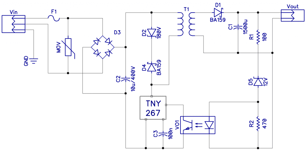
The Vin input s the 100-300V AC input (can also be DC), and the input is protected by a fuse and a MOV (Metal Oxide Varistor) to protect the circuit from overvoltage spikes. The D3 bridge rectifier and C2 capacitor together rectify the input AC signal into 100-300V DC. The output voltage of this stage is about [input voltage * 1.4] due to RMS values.
The D2 and D4 together form a transient suppression circuit to protect the TNY267 from back EMF spikes. D1 and C1 rectify the secondary output of the T1 transformer, which is the desired output voltage.
R1, D5, and R2 form the feedback circuit to regulate the output voltage according to varying load conditions. This helps the TNY267 to keep the output voltage constant at 12V.
Advantages and Disadvantages of Switched Mode Power Supplies
Switched-mode power supplies have many advantages:
- Smaller in size therefore can fit into compact devices
- Due to the semiconductor-based components, SMPS is lighter in weight
- Very efficient than linear power supplies (70-95% typical)
- Supports wider input and output voltage ranges
- Provides additional functions like adjustable outputs and safety functions as a short circuit, over-voltage, over current, and over-temperature lockout protection
- Lower heat dissipation, thus requiring minimal active cooling
However, SMPS also have drawbacks that sometimes make them unsuitable for certain applications. For example, a SMPS is a much more complex circuit than a traditional linear circuit. Therefore, there are many components that can malfunction and hinder the performance of the power supply.
Also, SMPS are known for their higher EMI (Electromagnetic Interference) and electrical noise since they work in high frequencies. A poorly designed SMPS can cause glitches and sometimes even permanently damage sensitive electronics powered by them.
In the power realm, switched-mode power supplies also create harmonic distortion in the power grid and sometimes may require additional power factor correction if they are not built-in to the supply.
Linear vs Switched Mode Power Supply
The main difference between the SMPS and linear supplies is their efficiency. Switched-mode power supplies are extremely efficient when compared with linear power supplies, which tend to dissipate more energy as heat.
Linear AC-DC power supplies typically use transformers to step down the input AC voltage and then rectify it using diodes and filters using capacitors. This provides a very low ripple output, but at the cost of reduced efficiency (around 30%-60%). They also tend to be very bulky in size due to the transformer’s size and weight. Linear power supplies can not handle varying input voltages if not specially designed.
On the other hand, linear DC-DC converters step down the voltage by dissipating the dropped voltage as heat. Therefore, high current linear regulators require more sophisticated, active cooling to function properly. However, linear supplies are simple inaction, and relatively low cost to implement. Also, the outputs of linear (transformer-based) supplies are isolated.
SMPS in this case excels with efficiency ratings ranging from 80% and above with minimal power losses. Also, they are small in form factor, and have flexible applications as the circuit can be altered to obtain adjustable outputs and even isolated outputs. But they are much more complex in design (high component count) and have high-frequency noise in the output. If not properly addressed, they can cause problems in the sensitive sections of the load circuits.
Conclusion
Switched-mode power supplies are very efficient in converting electrical power from one voltage to another. They are suitable for high efficiency, high power applications and in many cases, are more suitable than linear supplies. However, selecting an SMPS or a linear power supply should be carried out by considering many factors like an acceptable ripple in the output, load and line regulation, and the cost/complexity in the desired application.

