Introduction
The Basics of Linear Power Supplies
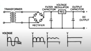
How Linear Power Supplies Work
-
Transformer: Imagine the input AC voltage is 120V RMS (root mean square), typical for household voltage in many countries. The transformer steps this down to, say, 12V RMS. This is an alternating current with a peak voltage of around 16.9V (since peak voltage ( V_p = V_{RMS} \times \sqrt{2} )), which you see in the first waveform.
-
Rectifier: The 12V AC is fed into a bridge rectifier. The rectifier flips the negative half of the AC cycle up to align with the positive half, resulting in a pulsating DC with a peak of 16.9V. However, it’s not a steady DC yet; it still has a significant AC component, as shown by the second waveform which has peaks but no longer dips below the horizontal axis.
-
Filter Capacitor: A filter capacitor (for example, 1000 microfarads) is placed across the output of the rectifier. It charges up to the peak voltage (16.9V) quickly and releases energy slowly when the input voltage drops, thus ‘filling in’ the valleys of the waveform. The voltage might still drop to, say, 15V before the next peak, which is illustrated in the third waveform as having less pronounced dips than the previous waveform.
-
Voltage Regulator: This stage takes the smoothed but still somewhat rippled DC voltage and regulates it down to a steady value. Let’s say the output we want is 9V DC. The voltage regulator will take the varying input (15V to 16.9V) and output a constant 9V. The fluctuation in input is absorbed by the regulator’s internal resistance, which varies to maintain the output voltage. The waveform is now a flat line, indicating a stable DC output with negligible ripple.
-
Output Capacitor: Finally, an output capacitor might be added to smooth any minute ripple that the regulator didn’t entirely eliminate and to handle any rapid changes in the load that might momentarily affect the output voltage. This ensures that devices receive a clean 9V DC.
Advantages of Linear Power Supplies
-
Low noise output
-
Excellent voltage regulation
-
Simple design
-
Good transient response
-
Minimal EMI radiation
Limitations of Linear Power Supplies
-
Inefficient
-
Large size and weight
-
Significant heat generation
-
Limited power capacity
-
Higher operational cost
The Basics of Switching Power Supplies
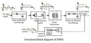
Working Principle of Switching Power Supplies
-
AC Input Supply: Assume the input is an AC supply with a voltage of 230V at a frequency of 50Hz.
-
Input Rectification and Filtering: This AC supply is passed through a rectifier and filter. The rectifier converts the AC into DC. Assuming ideal conditions, the peak DC voltage after rectification would be around 325V DC, because the peak of an AC signal is ( V_{RMS} \times \sqrt{2} ), where ( V_{RMS} ) is the root-mean-square voltage of the AC supply.
-
High-Frequency Switch: This DC is then fed into a high-frequency switch. Let’s say the switch operates at a frequency of 50kHz. It chops the DC into a high-frequency pulse train, where the width of the pulses corresponds to the desired output voltage.
-
Duty Cycle Control: The duty cycle (the ratio of the ‘on’ time to the total period of the signal) of these pulses is managed by the control circuitry. For instance, if the output needs to be 12V, the duty cycle will be set such that the average value of the pulsed output from the transformer corresponds to 12V.
-
Power Transformer: The transformer is designed to operate at the high frequency of the switch. It steps down the voltage accordingly. So if we have a 325V pulse input and we need a 12V output, the transformer will have a turns ratio set to step down the voltage to the desired level.
-
Output Rectification and Filtering: The AC current, once modulated by the transformer, undergoes rectification and is subsequently smoothed through filtration, resulting in a consistent DC current. Presuming the design is for a 12V output, the voltage at this juncture is expected to be a stable 12V direct current.
-
PWM and Oscillator: The PWM controller, which is regulated by an oscillator, dictates the duty cycle of the high-frequency switch, establishing the exact frequency and duty cycle to achieve the targeted output voltage and current.
-
Feedback Loop: Typically, a feedback mechanism from the output connects to the PWM controller, enabling the SMPS to tweak the duty cycle and keep the output voltage constant. So, if the voltage falls under 12V, this feedback will prompt the PWM to enhance the duty cycle, which boosts the energy per pulse and raises the voltage back to 12V.
Advantages of Switching Power Supplies
-
Enhanced efficiency
-
Reduced dimensions and decreased heft
-
Expansive range of acceptable input voltages
-
Amplified power capability
-
Diminished running expenses as time progresses
Limitations of Switching Power Supplies
-
Complex design
-
Higher noise output
-
Potential EMI issues
-
More complex EMI filtering required
-
Less suitable for very sensitive analog applications
Comparing the Performance: Switching vs Linear Power Supplies
Switching power supplies are the epitome of a good design that harnesses a control circuit and a switching device, typically a power transistor, to convert electrical power with high efficiency. Their ability to handle primary AC voltage and convert it to a stable output DC voltage with excellent regulation is like the adaptability of a hybrid car. The smaller size and lighter weight of switching supplies make them favorable in space-constrained environments, notwithstanding their slightly higher cost. They employ a small transformer, unlike the large transformer found in linear types, which contributes to their compact form factor.
Linear power supplies, conversely, are often synonymous with lower voltage applications. They operate by reducing the high voltage AC to a lower level using a rectifier circuit, followed by a smoothing circuit to deliver a near-constant DC voltage. Their larger size is due to the iron core transformers and series power supplies components, which, while contributing to lower efficiency, ensure the delivery of a stable voltage. This stability, along with the production of minimal noise, makes them well-suited for sensitive equipment.
However, linear power supplies are marked by their lower efficiency, leading to higher operational costs over time, especially evident under varying load conditions. They dissipate more heat, which might necessitate additional cooling measures, contrasting with the nimble and cooler operation of switching power supplies.
In conclusion, the choice between switching and linear power supplies boils down to the specific requirements of the application—whether the priority is for a smaller size and higher efficiency or for excellent regulation and stable voltage with minimal noise. Both types have their place, with switching supplies often being the go-to for efficiency and compactness, while linear supplies remain the bastion of stability and noise control, despite their larger size and lower efficiency.
Application Specific Considerations
-
For sensitive analog circuits, where low noise is crucial.
-
In applications requiring excellent voltage regulation and stability.
-
Where simple design and ease of maintenance are important.
-
When a good transient response is needed.
-
In situations where minimal EMI radiation is a must, such as precision testing or audio applications.
-
When high efficiency and energy savings are priorities.
-
On portable devices or when space and weight are limited.
-
For a wide input voltage range, accommodating variable power sources.
-
In high-power applications beyond the practical limits of linear supplies.
-
Where lower operational costs and energy consumption are desired over time.
Cost Implications and Power Ratings
Cost Comparison
|
Parameter
|
Linear Power Supply
|
Switching Power Supply
|
|
Component Cost
|
Generally higher due to larger transformers and heat sinks
|
Lower due to smaller components
|
|
Efficiency
|
Less efficient, more wasted energy than heat
|
More efficient, less energy wasted
|
|
Operating Cost
|
Higher over time due to energy loss
|
Lower due to better efficiency
|
|
Scalability
|
Not cost-effective at higher power ratings
|
More cost-effective as power ratings increase
|
Power Ratings
|
Parameter
|
Linear Power Supply
|
Switching Power Supply
|
|
Output Power Range
|
Typically lower, up to hundreds of watts
|
Higher, can handle up to kilowatts
|
|
Regulation
|
Very good at low frequencies
|
Good across a wide frequency range
|
|
Noise
|
Low electromagnetic interference
|
Can generate more noise, but manageable with design
|
|
Heat Generation
|
Higher, requires more cooling
|
Lower, more compact heat management
|

